
2.4 Programming Fundamentals — the Block Model
2.4 Programming Fundamentals — the Block Model
In this lesson: you will be able to explain the block-based programming model and read/edit the basic I/O blocks — UI, AO, DO — including point names and engineering units.
The block model
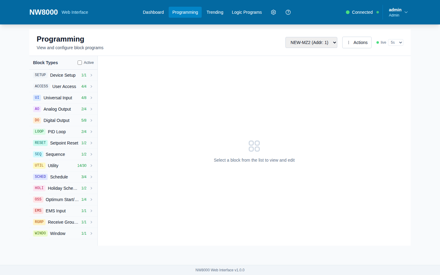
Network 8000 controllers use a block-based model, and once it clicks, the whole system makes sense. A controller program is a set of function blocks wired together. A Microzone II has sixty-nine blocks across thirteen types. Each block does one job — read a sensor, run a PID loop, drive an output — and blocks pass values to each other by pointers. For now, think of a block as a little function with inputs, parameters, and outputs.
The thirteen block types at a glance
- Input/output blocks: UI (Universal Inputs, 8), AO (Analog Outputs, 4), DO (Digital Outputs, 8).
- Control blocks: LOOP (PID), SCHED (schedules), HOLI (holidays), RESET, SEQ (sequencing), OSS (optimum start-stop), and UTIL (30 general-purpose utility blocks).
- Manager-facing blocks: WINDO (exports this controller's values up to a parent manager), EMS (receives values from a parent), and RGRP (receives group broadcasts).
Do not memorise all of them today — the advanced ones come one at a time in the next lesson.
The three you will touch most
- A UI (Universal Input) reads one sensor. Key settings: the name (up to eight characters, the label operators see), the input type (thermistor, Balco, platinum, 4–20 mA, 0–5 V, a digital contact, a pulse counter, and so on), and the engineering units. Set the input type to match the physical sensor — get that wrong and the reading is meaningless. Setting the input type to “not used” disables the input.
- An AO (Analog Output) drives a modulating device: a valve, damper, or variable-speed drive. Besides the name, an AO scales an input range to an output range — input minimum and maximum, output minimum and maximum — and has a stroke time so the gateway knows how fast the device travels.
- A DO (Digital Output) is a relay: on or off. Its key setting is the action — not used, direct, or reverse. Direct means the output follows its input; reverse inverts it. That one setting decides whether energising the relay means “on” or “off,” so choose deliberately.
Two habits from the manuals. First, point names are how everyone else reads the system — operators, BACnet clients, trends — so name things clearly and consistently. Second, every block has an enable: a UI's input type, a DO's action, an AO's enable flag. A block that is “not used” simply does not run. Programming is above the Operator level — you do this as a Technician or Admin.
Key points
- A Microzone II program is 69 blocks across 13 types, wired together by pointers.
- UI reads a sensor; AO drives a modulating device; DO drives an on/off relay.
- A UI's input type must match the physical sensor, or the reading is meaningless; “not used” disables it.
- A DO's action (not used / direct / reverse) decides whether the output follows or inverts its input.
- Name points clearly — operators, BACnet clients, and trends all read those names.
Check your understanding
- How many block types does a Microzone II program use, and roughly how many blocks total?
- Which block reads a sensor, which drives a modulating device, and which drives an on/off relay?
- On a DO, what does the “action” setting (not used / direct / reverse) decide?
- Why does setting a UI's input type correctly matter?